Plate Type Heat Exchanger
- Home
- Equipment and Ability
- Plate Heat Exchanger Design

Working Principle
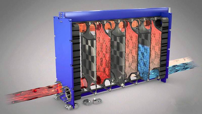
Channels are formed between the plates and the corner ports are arranged so that two media flow through alternate channels. The heat is transferred through the plate between the channels, and complete counter-current flow is created for the highest possible efficiency. The corrugation of the plates provides the passage between the plates, supports each plate against the adjacent one and enhances the turbulence, resulting in efficient heat transfer.
General Consideration
Plate type heat exchangers (PHE) consist of a number of parallel flow channels, formed by adjacent metal plates that are either welded or separated by gasket material around the perimeter of each plate. The plates can be formed from a variety of metals, but typically are made of stainless steel. The manufacturing process presses the plates into a corrugated shape that is different for each plate type and is proprietary to each manufacturer. The corrugations (sometimes called ribs or chevrons) both increase the mixing of the flow stream and add strength and support to the plate. The flow channel width between adjacent plates ranges from 0.05 to 0.25 in. (1.27 to 6.35 mm) and the ribs of adjacent plates have a contact point with each other at regular intervals. PHEs can be designed for true counterflow because the hot and cold flow streams pass through adjacent channels over the entire length of the exchanger. This design allows closer approach temperatures than are possible with conventional shell and tube exchangers. The assembly of PHE facilities mechanical cleaning and allows the addition or removal of plates to increase or decrease the heat transfer surface area of the exchanger. The main advantages of PHE are their compact size and high heat transfer effectiveness that allow the reduced number of units, smaller spaces and, for offshore platforms, and reduced weight. They are especially attractive in cost when the equivalent shell and tube exchanger would require an alloy shell or tubes. The minimum recommended construction material for all types of PHEs and welded PHEs is typing 304 stainless steel. PHEs are presently operating in such liquid-liquid services as heat recovery loops, chemical process coolers and heaters, oil platform applications, and seawater cooling. Partially welded PHEs make good applications in product coolers using cooling water. The plate and frame heat exchanger is not specifically considered, because steady-state design follows standard contraflow or parallel flow procedures. It is only necessary to source sets of heat transfer and flows friction correlations before proceeding. plate and frame heat exchanger design can be similar in flow arrangement to plate-fin designs, but there is the restriction on the piping manifold geometry. Optimization may proceed in a similar way as for compact plate-fin heat exchangers but is likely to be less comprehensive until universal correlations for the best plate panel corrugations become available. Significant features are composed of metal formed thin plates separated by gaskets. Compact, easy to clean. Application best suited is viscous fluids, corrosive fluids, slurries, high heat transfer. The limitation is not well suited for boiling or condensing; limit 35-500oF by gaskets. Used for liquid-liquid only; not gas-gas. Approximate relative cost in carbon steel construction 0.8 – 1.5. Inlet and return heading for plate and frame designs, and the same arrangement for plate-fin designs, may add a phase shift to the outlet transient response following and inlet disturbance. Plate type exchangers consist of a number of parallel flow channels, formed by adjacent metal plates that are either welded or separated by gasket material around the perimeter of each plate. The plates can be formed from a variety of metals, but typically are made of stainless steel. The manufacturing process presses the plates into a corrugated shape that is different for each plate type and is proprietary to each manufacturer. The corrugation (sometimes called ribs or chevrons) both increase the mixing of the flow stream and add strength and support to the plate.
Plate Heat Exchanger Design Procedures
- Calculate duty, the rate of heat transfer required.
- If the specification is incomplete, determine the unknown fluid temperature or fluid flow rate from a heat balance.
- Calculate the log mean temperature difference, ΔTlm.
- Determine the log mean temperature correction factor, Ft.
- Calculate the corrected mean temperature difference ΔTm = Ft x ΔTlm.
- Estimate the overall heat transfer coefficient.
- Calculate the surface area required.
- Determined the number of plates required = total surface area/area of one plate.
- Decide the flow arrangement and number of passes.
- Calculate the film heat transfer coefficients for each stream.
- Calculate the overall coefficient, allowing for fouling factors.
- Compared the calculated with the assumed overall coefficient. If satisfactory, say -10% to +10% error, proceed. If unsatisfactory, return to step 8 and increase or decrease the number of plates.
- Check the pressure drop for each stream.
